

- ARDUINO LED MATRIX MAX7219 HOW TO
- ARDUINO LED MATRIX MAX7219 DRIVERS
- ARDUINO LED MATRIX MAX7219 DRIVER
- ARDUINO LED MATRIX MAX7219 SOFTWARE
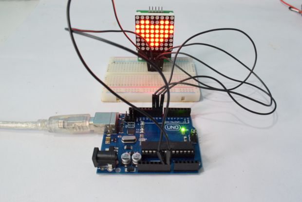
The wiring diagram below shows you how to connect the MAX7219 LED dot matrix display to the Arduino. Note that for this tutorial I used pin 3 (see table below). You can select any of the digital pins of the Arduino for the SS/CS pin. VCC, GND, CLK, and CS are shared between all of the displays. You can daisy chain multiple displays to create one large display by connecting DOUT of the first display to DIN of the next display.
ARDUINO LED MATRIX MAX7219 SOFTWARE
This interface is faster than using software SPI, but you will need to use the following fixed output pins: Hardware SPI pin locations Board The hardware SPI pins (MOSI, MISO, and SCK) are at a specific location on each Arduino board. You can control the display either through the Arduino’s AVR microcontroller hardware SPI interface or three arbitrary digital pins (software SPI). With an SPI interface there is always one master device (the Arduino) that controls the peripheral devices (also known as slaves). To learn more about this data protocol, please see this page on the Arduino website.

ARDUINO LED MATRIX MAX7219 DRIVER
The MAX7219 LED display driver communicates with the Arduino through SPI (Serial Peripheral Interface). How to connect the dot matrix display to the Arduino MAX7219 LED dot matrix display specifications Operating voltageįor more information, you can check out the datasheet: Still, you only need three wires to control all of the ICs so you need very few I/O pins of the Arduino.īelow you can find the specifications of a typical MAX7219 8×32 LED dot matrix display.
ARDUINO LED MATRIX MAX7219 DRIVERS
However, you can daisy chain multiple drivers and matrices together and easily control much larger displays like 8×32, 8×64, or even bigger. Since the MAX7219 can control a maximum of 64 LEDs, the maximum size dot matrix display it can drive is 8×8 pixels. The driver communicates with the Arduino through SPI so you only need three wires to control the display. The MAX7219 LED driver can be used to control 7-segment displays up to 8 digits, bar-graph displays, or 64 individual LEDs. As an Amazon Associate we earn from qualifying purchases. is a participant in the Amazon Services LLC Associates Program, an affiliate advertising program designed to provide a means for sites to earn advertising fees by advertising and linking to products on. Generic 8×8 MAX7219 LED dot matrix display (alternative)

If you have any questions, please leave a comment below.Ĩ×8 MAX7219 LED dot matrix display (alternative) How to control a character I2C LCD with Arduino.How to use a 16×2 character LCD with Arduino.TM1637 4 Digit 7 Segment Display Arduino Tutorial.Other Useful Links From Around The Web:.Basic Arduino example code to print text.Different types of LED dot matrix displays.Installing the MD_Parola and MD_MAX72XX Arduino libraries.MAX7219 LED dot matrix display connections.How to connect the dot matrix display to the Arduino.MAX7219 LED dot matrix display specifications.


 0 kommentar(er)
